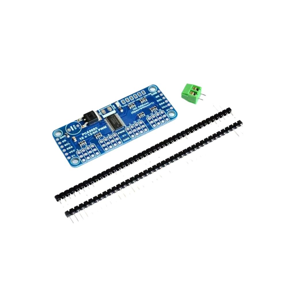
### PWM/Servo Driver – I2C Interface – PCA9685 Overview
1. **Type**: PWM/Servo Driver with I2C Interface
2. **Specifications**:
– **IC Model**: PCA9685
– **Interface**: I2C (Inter-Integrated Circuit)
– **Number of Channels**: 16 PWM channels
– **PWM Frequency**: Adjustable from 24 Hz to 1526 Hz (default 50 Hz for servo motors)
– **Resolution**: 12-bit (4096 steps per channel)
– **Power Supply**: Typically 5V DC
3. **Material**:
– **Chip**: Silicon IC with integrated circuitry for PWM control
– **PCB**: Printed circuit board with connectors for I2C and servo connections
4. **Functionality**:
– **PWM Generation**: Provides precise Pulse Width Modulation (PWM) signals for controlling servos, LEDs, and other devices.
– **I2C Communication**: Allows control of multiple PCA9685 chips using a single I2C bus, with addresses assigned via jumpers or pins.
– **Servo Control**: Ideal for driving up to 16 servos simultaneously with independent control of each servo’s position.
5. **Features**:
– **High Resolution**: 12-bit resolution allows for fine control of PWM signals.
– **Adjustable Frequency**: Frequency can be adjusted for various applications, including servos and LEDs.
– **Multiple Boards**: Multiple PCA9685 boards can be connected on the same I2C bus, expanding the number of controlled channels.
– **Built-in Oscillator**: Includes a built-in oscillator for generating stable PWM signals.
### Typical Uses:
– **Servo Control**: Ideal for robotic arms, UAVs, and other projects requiring precise servo control.
– **LED Lighting**: Can be used for controlling LED brightness and effects in lighting projects.
– **Automated Systems**: Used in systems requiring precise timing and control of multiple outputs.
### Key Benefits:
– **Precision Control**: Provides high-resolution PWM signals for accurate control of servos and other devices.
– **Ease of Use**: I2C interface simplifies communication and control of multiple devices using a single bus.
– **Expandability**: Multiple PCA9685 modules can be daisy-chained to increase the number of controlled channels.
### How to Use:
1. **Connect to I2C Bus**: Wire the PCA9685 to an I2C bus on a microcontroller or single-board computer, like an Arduino or Raspberry Pi.
2. **Power Supply**: Connect the power supply (typically 5V) to the PCA9685 board.
3. **Configure I2C Address**: Set the I2C address using jumpers or pins on the PCA9685 to avoid address conflicts if multiple boards are used.
4. **Initialize and Control**: Use a suitable library or write code to initialize the PCA9685 and control the PWM outputs via I2C commands.
### Example Applications:
– **Robotic Projects**: Control multiple servos for robotic arms, drones, or automated vehicles.
– **Home Automation**: Use for controlling automated blinds, curtains, or other devices requiring precise control.
– **Lighting Systems**: Manage LED arrays with adjustable brightness and effects.
### Installation Tips:
– **Verify Connections**: Ensure all connections, especially I2C and power, are secure and correctly oriented.
– **Check Addressing**: Ensure that each PCA9685 on the I2C bus has a unique address to avoid conflicts.
– **Use Libraries**: Utilize existing libraries for popular microcontrollers (e.g., Adafruit?s PCA9685 library for Arduino) to simplify coding and setup.
### Advantages:
– **High Resolution and Precision**: Allows fine control over PWM signals with 12-bit resolution.
– **Scalability**: Easily expand the number of controlled channels by adding more PCA9685 boards.
– **Versatility**: Suitable for a wide range of applications including servos, LEDs, and more.
The PCA9685 PWM/Servo Driver with I2C interface is a versatile and powerful tool for precise control of multiple PWM outputs. Its high resolution and expandability make it suitable for complex projects requiring detailed control and coordination.


Reviews
Clear filtersThere are no reviews yet.