Popular Categories
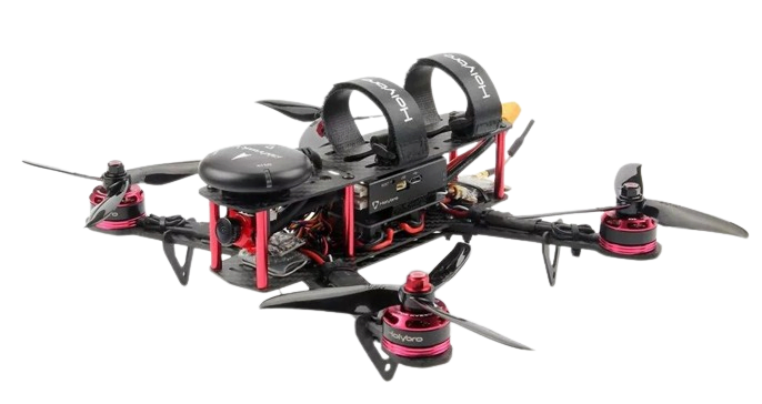
DIY Drone Event
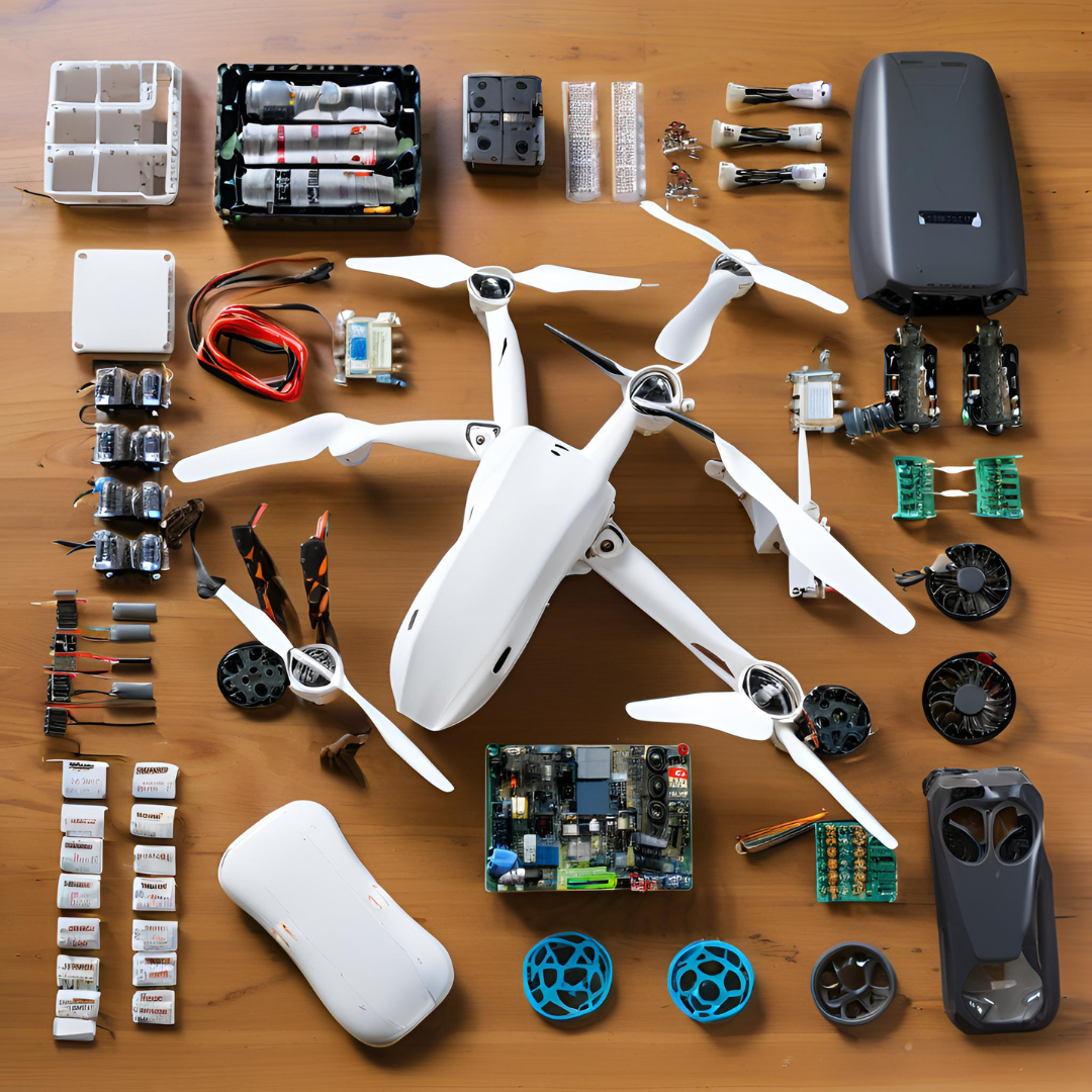
Hurry and get discounts on all Drone Accessories up to 20%
0
days
00
hr
00
min
00
sc
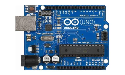
Arduino Accessories
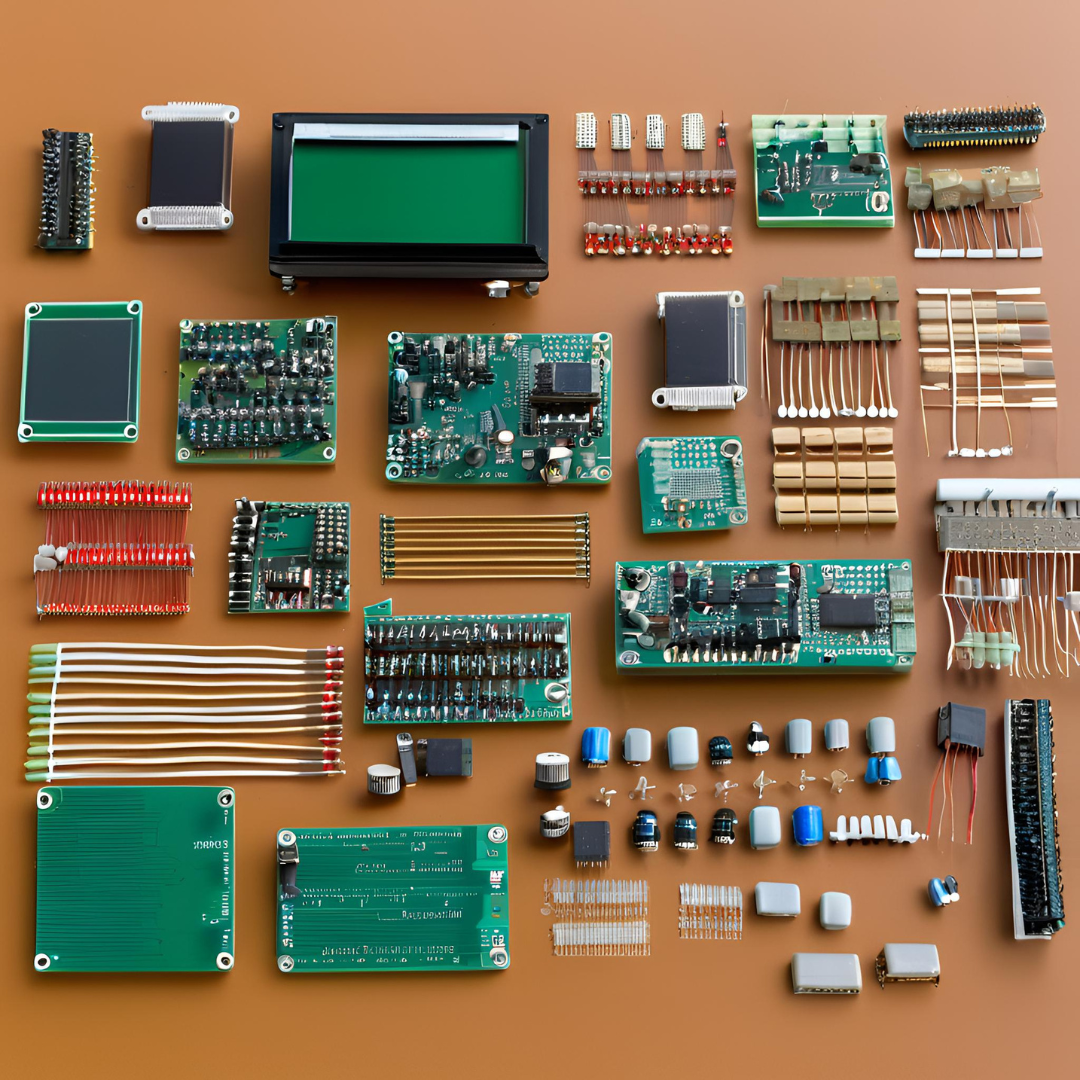
Personalize your Arduino with a variety of accessories to match your unique style. With an array of colors and designs, there's something for every taste. Whether you're a beginner or a seasoned pro, our selection of Arduino accessories will help you stand out and bring your projects to life.
Recently Viewed
Our Articles
Supercharge Your Storage in 2024: Raspberry Pi 5 Hat+ NVME – Boost Your Storage!
The Raspberry Pi 5, with the introduction of the $12 M.2 HAT+, has revolutionized the way we approach storage ...
DIY RC Car – Fast and Power Packed in 2024
Welcome to the ultimate guide on building a DIY RC Car that is both fast and power-packed! In this article, we...
Ultimate DIY RC Transmitter – Elevate Your RC Projects in 2024
In this tutorial, we will learn how to build a DIY Arduino RC transmitter . Often, wireless control is essenti...
Ultimate Guide: Interfacing a Water Level Indicator with Arduino in 2024 (Connections & Code)
In the article 'Water Level Indicator: Interfacing With Arduino - Connection and Code', we explore the compreh...
Effortlessly Installing OpenCV using CMake on Raspberry Pi in 2024
Installing OpenCV on a Raspberry Pi using CMake is a practical approach for those looking to utilize OpenCV's ...
Advanced Robotics and Smart Devices Store
The platform also features educational resources and customer support to assist users in making informed decisions and effectively utilizing their purchases.


